|
|
Post by scooby on Jul 18, 2013 9:51:12 GMT
Plans for the RV. Thanks to this forum and AndyEx-RVMac, I’ve got myself what I was looking for; a nicely-running, ready-to-use, RV but with even more potential! My kids LOVE it, and even my wife is surprised at how comfy and roomy a kit-car can be. My medium-term plans at the moment are: 1) Replace the hardtop with a ‘sectional’ roof and ‘folding’ doors, so that the RV can be run in various stages of undress. I’m really not keen on hard-tops (my Marlin had one); I dislike the way you’re committed to being covered whenever you set off on a fairly-dodgy-weather day. The rain will invariably stop at some point, but you’ll still be trapped inside a fibreglass tub – hardly the point of these cars. My thoughts are to try and make a partly-hard and partly-soft roof; I'm thinking the rear side panels will best be solid-but-light, and can be used on their own if wanted. I think I'll also explore having a flat roof 'bar' going over the top where the roll-over bar goes across, so it'll be a bit like a Vitara. The main roof could then, perhaps, be made from two separate ‘soft-top’ panels going over the top and down the back to complete the roof when it’s really piddling. The idea is that various sections can be removed and stored in the car depending on how brave you are. Hmmm, the soft top could even be rolled back from the front in stages like on a 2CV… These are just thoughts at this stage. The new doors will be ‘solid’, hopefully very. For ease of making, I’m thinking a double layer of 18mm marine ply, with a thinner ply layer on the outside overlapping it so’s it acts as the outer skin of the door and fit nicely in the moulding recess on the outside. Marine ply is strong stuff and a 36mm thickness should look – and be – sturdily substantial. It should also allow me to cut out a large window opening, shaped like the Wrangler Jeep’s – ie: sloping frame at the front to get away from the usual ‘rectangular’ side window look. 2-part sliding windows (acrylic) can be cut to fit neatly, and the overall window width should mean that either section slid open should give a good-sized aperture. But, an idea I’m really keen on trying is to also have the whole top ‘window’ half of the door sliced horizontally like ‘barn’ doors, hinged and fold-flatable against the lower section on the outside for really warm days. A clip will hopefully stop it flapping like wings… The ‘fold’ could be at elbow-rest height! Again, just thoughts at the mo’… 2) Interior: No offence at all to Mr Mac; he’s done a very neat job of the dashboard. I am looking to do something more ‘production’-quality, tho’, so that the Cortina binnacle is fully ‘disguised’ as they were in my Marlin. At the same time, I’d like it to be truly unique to my RV, so that rules out shoe-horning in an existing production-vehicle dashboard, even tho’ I’ve seen some cracking examples of Sierra dashboards being used in RVs. Thoughts of carbon-fibre texture for the panel and ‘suede’ for a non-reflective top cover are being mulled at the mo’… An idea I used successfully in the Marlin was a way of hiding your ICE. I doubt anyone here is going to fit a high-quality stereo system in such a ‘vulnerable’ car? What I did in the Marlin was to buy a ‘power-amp’ (the type used to boost the outputs of existing stereos) which can be bought for next-to-no money 2nd-hand on t’Bay. This can be mounted anywhere, even in the engine bay, although behind the dash would be usual. Speakers can similarly be mounted pretty much out-of-sight (the sides of the foot-wells look promising in the RV), and it’s all wired up. All you then need on the dash is a single on/off switch and a 3.5mm jack socket. Plug your MP3/iPod/phone/portable CD/radio/whatever in - using a short fly-lead from the headphone socket - switch on, and you have instant ICE. All controls accessed on your player. Ok, not a good idea to be fiddling with your MP3 on the move, so I think I’ll also add a volume control on the dash this time – any other adjustments can wait until I stop (in any case, mine will be permanently set to Radio 4…) 3) Heater: I’ve been looking at to how to best approach this task, and I think the simplest & cheapest way is to go ‘bespoke’. You can pick up heater matrices for a £iver (see what I did there…? sigh) and blowers for a similar amount. If space is at a premium, then the blower can be mounted under the bonnet, with an intake duct grabbing fresh air (not oily fumes…) from the under-arch if necessary. The matrix can be mounted inside a simple box made from 6mm MDF or similar (max temps are going to be well below ‘boiling’, so no hardship for that material). With an MDF case, you can shape it to fit neatly under the dash just where you want it, rather than having to try and adapt a production-car unit. What’s the worst part about fitting heaters? Yep – the controls; a nightmare. Levers and cables? Yuck. I’m hoping I have a solution here too; I’ve seen what looks like electrically-operated flow valves which are used on modern cars such as the Focus, so the hot/cold option could hopefully be controlled by a single electrical switch on the dash. One more switch for the fan, and that’s the heater controls taken care of  . Except one… ![unsure[1]](//storage.proboards.com/658221/images/6Gy1jIcXxHETTCw1CY9x.gif) To get the warm/cold air to where you want it, I have an even simpler mechanical solution; just fit a couple of directionable and on-offable eyeball vents at the bottom-front of the casing where they can easily be reached - this will supply the hot or cold air to the cabin. A single hose run from the casing up to windscreen vents will provide demisting. So, with the eyeballs open, most of the air will come straight out into the cabin, but if greater windscreen demisting is required, just shut off the eyeballs! No levers, no remote controls. I’m really hoping all that’s needed is one fan switch and one hot/cold switch - as well as the two balls… Did I say these are just thoughts at the moment…?! Once all this starts, I will of course post the progress on here in case these projects are of interest. |
|
|
|
Post by Peter on Jul 18, 2013 23:30:32 GMT
Hi Scooby, great you found your ideal car, I hope we see progress photos soon, sounds like a well sorted bases for a great car. ![rock[1]](//storage.proboards.com/658221/images/WwlTZGzEzqS029BPkumN.gif) Have a look at the way the Suzuki Vitara (old model like 1995, had a detachable hard roof up front and option hard or soft at the rear, I had both on mine. |
|
|
|
Post by scooby on Jul 19, 2013 8:53:20 GMT
Thanks. I've seen a few Vitaras around, and that's where I got the idea of the flat bar across. Hmm, a hard panel for the front - that could be a neat idea.
|
|
|
|
Post by scooby on Jul 24, 2013 13:27:28 GMT
|
|
|
|
Post by Peter on Jul 24, 2013 15:48:21 GMT
Love it.. but has to be RED!
|
|
|
|
Post by scooby on Jul 24, 2013 15:56:47 GMT
|
|
|
|
Post by scooby on Aug 28, 2013 23:50:53 GMT
No major changes yet. Just been tweaking and tidying bits and pieces, especially the wiring as it's been giving me a real headache... The original Cortina harness at the rear was a mass of terminals, splices, tape, blocks and additional wires. (No reflection on the previous owner - it looks as tho' it was like this from its first build!) Since I was planning to replace the rear light clusters, I thought I should sort this out at the same time, so I cut the whole loom shortly after it emerged from the bodyshell at the back, and this squirming mass of cables was re-bound and pushed into a waterproof JB tied to a chassis member. One single hefty earth cable was then bolted to a single chassis point and brought to this JB too - all the rear earthing requirements will now go through this single wire. Whilst trying to figure out which wire was which in this snake's pit of a loom, I left the indicators running so's I could trace the voltage. After a few seconds, the flash rate began to slow right down, finally stopping with the flasher relay emitting only a weak asthmatic wheeze as it tried in vain to 'click' one last time. Hey-ho, I'll sort that later...  From the new main JB, there now emerges a single, neat, 'trailer light' cable (with just 7 cores) which daisy-chains to the 2 new light clusters and a new trailer socket. Bizarrely, the indicator problem was traced (days later...) to a lack of earth to the warning lights in the instrument binnacle. That took some head scratching, but my suspicions fell on the instrument cluster when I decided it was time to rip off the whole dashboard (  , AndyEx-RvMac...) and I discovered the indicators started to flash ok when the 'clocks' weren't in place... Leccy is well strange stuff! The lack of earth here seems to have caused the leccy to find a path via the other circuits, such as the headlamp filaments, and this drain was enough to cause the flasher relay to say 'Non'. Trying to operate the indicators would get the main beam warning light coming on, and other strange things. Anyways, all the dashboard wiring loom has now been tidied too, with just the basic requirements left behind. The sad Cortina cluster now sits alone in a wide open space, held in place with gaffa-tape. Nice...The rear light units are Mazda RX7 units, strangely enough. Why them? Because they looked nifty in the eBay ad, were of the type they describe as 'Lexus Jewel' (which means they're sparkly and chromy - well bling...), looked fairly 'flat' (which you need for the Jeep's back) and - oh yeah - I got them brand new for 99p + delivery from an after-market light specialist... Ok, they needed around 3" cut off from the 'bottoms' (or the 'outsides' when fitted on the RX7), and also a little bit more fettling - and a darned big hole cut in the back of the car: 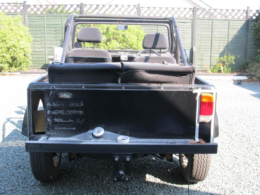 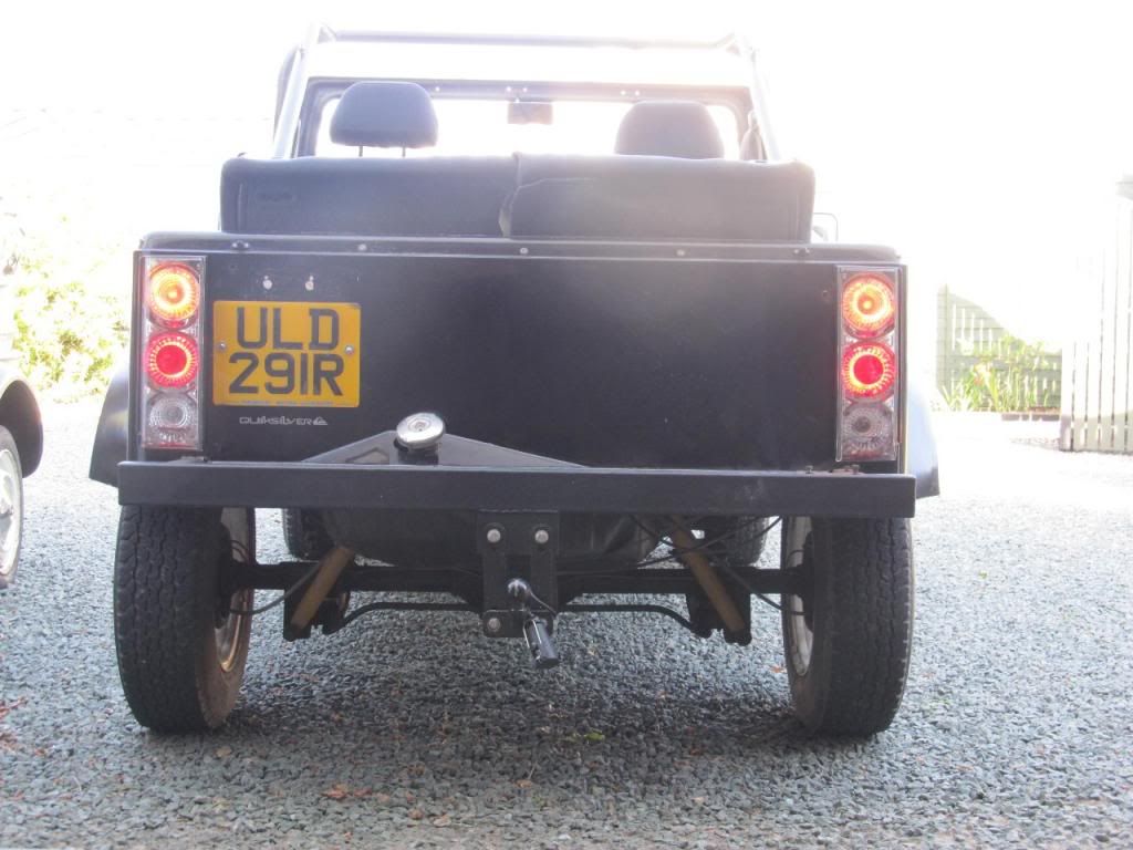 An electronic flasher unit and full quota of LED lamps are winging their way from China as I type. By using electronics and LEDs, running the trailer shouldn't cause any problems, and I'll also welcome the large fall in current draw. The rear end still looks a bit bare with the spare wheel rack temporarily removed, but another aspect of that view I'm planning to improve is by adding some 'bodywork' below the existing so's it hides the fuel tank and a bit of the suspension; I think it looks too much like a 'kit car' at the moment... Anything else? I tightened up the steering column as it was a bit shaky, bought a nice 'Mondeo' steering wheel of eBay (which I fitted by cutting off the Cortina wheel's 'boss' and bolting it to the Mondeo's after cutting the existing fitting of that wheel too...), and this makes a huge difference to the overall 'feel' of the car - both literally, and in it's appearance. I'm not really a fan of after-market steering wheels as they often look like they don't quite 'belong' - well, certainly not in a Jeep-style vehicle - and the quality of modern car wheels is pretty hard to beat. If it's good enough for a Mondeo... (This also means I have an air-bag detonator sitting in my garage, which I'm looking forward to firing... It has two little electrical plugs - I wonder which terminals I wire my battery to...?) Oh, and there's a 'new' (reconditioned by Delco Remy) steering rack (only £44) and track-rod ends sitting waiting to be fitted. There's a goodly half-inch of play in the existing, so I look forward to feeling the difference there too! Hey-ho. I'm loving the RV! It's so nice to have the SPACE inside after having to cope with the tiny cockpit of the Marlin and 2CV. It's so practical; everyone - and the dawg - just jumps in and offski. Come winter time, it'll be the same - no roof is going on. You put a coat on to go for a walk, so the same will apply here... |
|
|
|
Post by Peter on Aug 29, 2013 7:34:01 GMT
Great progress, amazing what can be done if you just get on with it. Definitely needs that rear valance, didn't realise the RV was that bare at the rear. ![hmmmm[1]](//storage.proboards.com/658221/images/XKN5ScdKR1O8cJ3IeDgW.gif) The lights are great, maybe a bit bling for a 'jeep' but, heck, they fit and work and your happy, just need to bring the rest of the car up to the same level. Crack on my son, look forward to seeing the end result. |
|
|
|
Post by scooby on Aug 29, 2013 10:18:59 GMT
"Valance"! That's the word  Yes, the lights are a bit loud, but tone down quite a bit with the wheel rack back on to fill that space. If they're still too 'noticeable' when the car is resprayed (haven't chosen colour yet...), then they could always be 'smoked'. I do love how clear the light output is, tho', especially after the seemingly weak glimmer of the old units. |
|
|
|
Post by Peter on Aug 29, 2013 13:09:29 GMT
Like it though, are you going for roughty-toughty or bling or somewhere in-between? Now, do they do Vauxhall Cavalier GL in those? |
|
|
|
Post by scooby on Aug 29, 2013 23:16:45 GMT
Definitely not bling (the lights ain't that bad in reality  ) but not roughty either - hopefully just a neat, well-finished, relaxed runabout which my wife will also be happy to use. The side zorts will be going...
|
|
|
|
Post by scooby on Sept 2, 2013 0:22:32 GMT
New (recon) steering rack and track-rod ends fitted, and that has really tightened up the steering nicely.
It's slightly lacking in self-centring at slow speeds, tho' it's not really a problem. I set the alignment using a quickly-cobbled home-made device (a timber beam the length of the car's track, with an upright at each end to match the wheel centre heights, and a long screw going through each which can be adjusted until they touch the wheel rim) to fractionally 'toe-out' as stated in the manual. Anyone know if a 'tweak' of this measurement might help perhaps as compensation of the wider track and larger wheels? I understand that self-centring is mostly down to 'castor' angle and not alignment, but asking chust in case!
It might just be down to the new rack's slight 'stiffness' - it really is 'snug' feeling, so it should loosen over a bit of time.
Anyways, looking at how to approach my new dash. The Cortina cluster is squeezed in tightly above the steering wheel and the bottom of the windscreen frame at the mo', and I'd ideally like it a bit higher. I glanced into a Mercedes ML Jeep t'other day, and noticed that its binnacle is mounted in a pod sat above the rest of the dash, going a few inches over the screen. Do'h! It never occurred to me that it would actually be ok to go over the screen a bit - you never look that low through it anyway...
That leads to a potential problem, tho' - routing the speedo cable. So, I'm pretty much decided I'm going 'electronic' - but, as always, on a tight budget.
I've just bought an 'electronic' Mondeo instrument cluster on eBay (tho' I have suspicions the guy ain't going to honour the sale as it went pretty cheap...) which I'm going to experiment on. I'm hoping that the rev counter and speedo would both be operated by simple 'pulses' similar to the current Cortina's rev-counter, but have a horrible feeling that the dials on these electronic dashes are driven by stepper-motors, so will require the full electronic jobbies to operate them...
So, another idea is - use 'Cortina'-type rev counters for both the tacho and speedo. These tachometers are simply powered by yer usual +ve and -ve supply, with the 'trigger' signal being delivered - I think - by a pull to 'zero' (or -ve). On the car, the rev counter signal wire is connected to the coil's 'negative' side, and this is pulled to zero volts (earth) each time the points close. So surely that's it?!
So, my idea is to have the speedo cable terminate inside a 'podule' under the bonnet with a rotating magnet attached and as many reed switches mounted around the circumference as is needed to provide roughly the right amount of pulses (a number I've no idea about at the moment, as I don't even know how fast the cable spins!). These reed switch outputs will be pulled 'high' by a resistor in its normal state, but will be connected to earth when the magnet flies past and closes them. (I could go the route of having a single reed switch and a few magnets, but I think a single magnet and a few switches will give each switch less work to do!)
The pulses from this will then operate the 'rev counter' and, when I arrive at the 'right' number of reed switches to use to give a roughly decent full-scale, I'll print up a speedo dial to suit.
Complete with 'Eagle' logo in t'middle...
Does anyone know anything about modern electronic production-car speedos? Am I talking nuts? Am I just nuts?
All good fun, tho'...
|
|
|
|
Post by scooby on Apr 13, 2014 21:59:53 GMT
Being very lazy recently, but finally sorted my rear brakes which have been causing weird problems for a while. Some symptoms included unpleasant 'clunks' and complete lock-up of the brakes when going from reverse braking to forward. Not a good thing to happen - I'm talking complete lock-up of a rear wheel whilst in motion... The causes was down to one of two things - I can't be any more specific since I had two problems within the same drum; return springs fitted in the wrong place and a lack of bump stop for the handbrake cable. (The absence of the latter allows the handbrake lever that's mounted on the shoe to land hard against the shoe securing spring when the handbrake is off. The spring was literally squashed flat in the middle. Anyways, redid one side with a complete new shoe set and fitting kit. Found it a complete pain due to rubbish Haynes manual instructions and fiddly securing fittings. Seems I'm not alone here as others both on this and on the BuySellCortina forum have also hated working on this braking system. Happy to report that second time around was very straight-forward, and here follows hopefully simple instructions for the job: 1) Jack, axle stand - wheel and drum offski. 2) You will be faced with this...  3) Next, remove the shoe retainers. For this you'll need a slotted tool as shown. I used an old screwdriver with a busted tip - I cut a shallow slot using a 4" angle grinder. You first need to peer into the spring hole or prise away the shoe to look behind it with a torch to see which way the 'end hook' of the spring exits the spring's coil - this will determine which direction you apply the disengaging force. (See the second last post of this article - on page 3 - for a proper picture of how this securing spring attaches.) If you look down from above, peering between the cylinder end and the start of the shoe, you can see the spring hoop and clip which really helps when operating the tool.  Insert this tool, locate it in the end spring loop as it crosses along the centre, push firmly inwards to extend the spring a few mm (it doesn't require tooo much force) and then lever the whole tool to the correct side to disengage the spring end from the backplate clip (see the picture much further on for a close-up of the spring and clip so's it makes sense). |
|
|
|
Post by scooby on Apr 13, 2014 22:01:56 GMT
4) Once both clips are removed, you then lever off the bottom shoe ends:  With both ends disengaged, the spring just lifts off...  |
|
|
|
Post by scooby on Apr 13, 2014 22:04:38 GMT
5) You repeat this process for the top spring. Just take GREAT care not to damage the rubber dust covers...  First one shoe and then t'other:  |
|
|
|
Post by scooby on Apr 13, 2014 22:08:13 GMT
6) Good news - there should be just enough room betwixt cylinder and hub to wriggle out the complete shoe assembly - just get that adjuster link past with a bit of shuffling around...  Pull it all back to expose the handbrake cable attachment, use a screwdriver to prise out the handbrake lever to allow you to detach the cable end:  |
|
|
|
Post by scooby on Apr 13, 2014 22:10:40 GMT
And here's the whole assembly:  7) To remove the top spring, you can use a wire loop to slip over the end and pull, or else just use a thin-bladed screwdriver to lever the end off:  |
|
|
|
Post by scooby on Apr 13, 2014 22:14:33 GMT
8) Here's all the new bits. The Haynes manual covers swapping all these bits around, but please ask if you have any questions:  9) Here's the new handbrake return spring sitting in place:  |
|
|
|
Post by scooby on Apr 13, 2014 22:24:16 GMT
10) To fit the link bar, first catch the end over that return spring:  And then lower the link down to sit correctly on the shoe:  |
|
|
|
Post by scooby on Apr 13, 2014 22:26:57 GMT
11) To locate the other end, first pull out the serrated brake adjuster lever as shown:  ...and slip the lever's end into the exposed slot:  |
|
|
|
Post by scooby on Apr 13, 2014 22:28:42 GMT
...before pushing the adjuster lever back into place, pulling the link with it:  (You need to pull out the other serrated adjuster thingy first, to allow this larger one to be pushed back fully against the back of the shoe.) |
|
|
|
Post by scooby on Apr 13, 2014 22:31:52 GMT
12) You now need to fit the TOP spring. NB This is the larger diameter - and 'softer' - spring!!!! This is actually not hard to do - my preferred method is to fit one end and then use a thin-bladed screwdriver over the other spring end to get it into place:  See? Not hard :-)  |
|
|
|
Post by scooby on Apr 13, 2014 22:35:54 GMT
This is the whole assembly (minus bottom spring) ready for fitting:  13) Now offer it all up to the back plate, levering out the handbrake lever with a screwdriver to allow the cable to be fitted:  |
|
|
|
Post by scooby on Apr 13, 2014 22:40:35 GMT
14) More shoogling around to get the upper link assembly back in past the hub - as before, it will go!  Wriggle...wriggle...wriggle...PLOP!  |
|
|
|
Post by scooby on Apr 13, 2014 22:45:04 GMT
15) Following a reversal of the dismantling process, to refit the shoes into place you now CAREFULLY lever one end onto a cylinder piston. This is where you need to take great care to not allow the shoe end to bite into the dust cover, or even cause damage with the lever you are using for the task. It isn't hard to do, and the levering doesn't take much force. Once you get one end on, use your hand to keep it there and not let it slip off as you lever the other end...  First one end, and then t'other...  |
|
|
|
Post by scooby on Apr 13, 2014 22:47:29 GMT
16) The bottom spring is even easier - bring the two ends close, and pop on the spring loosely:  And repeat your levering malarkey as before:  |
|
|
|
Post by scooby on Apr 13, 2014 22:57:27 GMT
17) Finally, fit the securing springs... As before, you need to check how the spring's end loop departs the main spring coil:  Engage your tool (ooh-er, missus)...  If you look at this picture, the hook at the top of the spring needs to be pushed over to the the left before being pushed further forwards and and then allowed to pop back to the right to engage in the clip (Bear in mind this happens 'blind' - so visualise what's happening as you do it). So, in this case you'd insert your tool, lever the tool's handle over to the right, push it just a few mm forwards (needs a firm-but-not-excessive push), and then lever the handle back to the left. At the same time, ensure the clip is kept tightly flat against the backplate with your other hand, 'cos if the clip moves or falls out even a tiny amount, you ain't going to catch it with the spring. AGAIN, LOOK DOWN BETWEEN THE PISTON END AND THE SHOE END - THERE IS A GAP THERE WHERE YOU CAN LOOK DOWN TO SEE THE SPRING GOING ON TO THE CLIP. THAT MAKES IT EASY-PEASY! The weird thing is, this task caused me to nearly weep with frustration the first time I tried it - when I didn't actually know what the clip even looked like and couldn't figure out what was actually happening hidden behind the shoe. As soon as I'd seen one removed, refitting it now is a 3-second affair - it spookily engages first time pretty much every time. |
|
|
|
Post by scooby on Apr 13, 2014 23:05:35 GMT
Jobby done. And it was a breeze second time around.  Refit the drum, check it isn't binding, refit wheel, and gently pump the foot brake. See that it works as it should be having someone turn the wheel whist you jab the pedal. Now try the handbrake - you really need both rear wheels off the ground simultaneously if you plan to adjust the cable. Enjoy  |
|
|
|
Post by scooby on Apr 22, 2014 18:03:21 GMT
And offski for an MOT.
And, having sorted out the rear brakes and also rebuilt the front callipers, and with a new steering rack and track-rod ends, I'm pleased to say none of these 'major' items failed.
The failure list was, nevertheless, pretty long... But all stuff I sort of knew was dodgy and was to be tackled as part of the refurb plan. Not surprisingly tho', the MOT cove - who did a thorough-but-fair job - isn't looking into the future like me, so insists them items are sorted now - ta very much.
Loose petrol filler neck... I know, I know.
Both headlamps delivering a serious squint, aiming as they are in an almost cross-eyed fashion.
Loose wiring harness under t'bonnet. Fairy nuff - I should have secured the loom after having tweaked/modified/traced/removed various weird cables.
Brake pipe needs further securing as it makes its way across the front sub-frame. Sheeesh - getting a bit pedantic, there. But I guess fair enough too.
And advisories: Handbrake outer cable touching against petrol tank. Fuel tank itself slightly loose. Wiring loom running up side of footwell close to throttle pedal and not properly secured.
No arguments there. All stuff that needs doing - and would have been in due course. But I appreciate the kick up t'rear to start work in earnest.
Lawd - I have such plans for the Jeep, and so many bits already bought for it - a new (quiet)exhaust, really nice side-steps, yummy 17" alloys and fat tyres to boot. Literally. And - always my ultimate fav part of a kit - a bespoke dashboard to design and make.
Must get going. Must. Must...
|
|
|
|
Post by scooby on Apr 29, 2014 18:32:41 GMT
MOT all good on the re-test. Phew...
|
|


 .
.![unsure[1]](http://storage.proboards.com/658221/images/6Gy1jIcXxHETTCw1CY9x.gif)

![rock[1]](http://storage.proboards.com/658221/images/WwlTZGzEzqS029BPkumN.gif)

 , AndyEx-RvMac...) and I discovered the indicators started to flash ok when the 'clocks' weren't in place... Leccy is well strange stuff! The lack of earth here seems to have caused the leccy to find a path via the other circuits, such as the headlamp filaments, and this drain was enough to cause the flasher relay to say 'Non'. Trying to operate the indicators would get the main beam warning light coming on, and other strange things.
![hmmmm[1]](http://storage.proboards.com/658221/images/XKN5ScdKR1O8cJ3IeDgW.gif)

 ) but not roughty either - hopefully just a neat, well-finished, relaxed runabout which my wife will also be happy to use. The side zorts will be going...


